Table of Contents
Skateboards are exposed to large static and dynamic loads imposed on them by the rider and the environment during their daily use. In this project, I design my own skateboard to meet the following requirements.
The skateboard must:
- Support a maximum load of during a worst-case scenario.
- Accommodate riders with shoe sizes up to 12.
- Have a factor of safety of at least 3.
Our goal is to minimize the weight of the skateboard while meeting these specifications.
Design Decisions
Following the general sizing guidelines found here, the deck size was chosen to to be long with a width to accommodate riders with larger shoe sizes. The kicktail angle was chosen to be 20 degrees to allow riders to “ollie” and perform other skateboarding tricks. To better grip the rider’s feet, a slight concave was added to the board. The skateboard wheelbase, as measured between the inside bolts of the deck was chosen to be . A larger wheelbase provides the skateboard with additional stability, especially at high speeds. A skateboard with a small wheelbase can begin to “speed wobble” at high speeds and endanger the rider. Because of the equation driven modeling style used in the CAD model, the skateboard deck dimensions and properties can be easily customized to the rider’s wishes. The CAD model is provided here.
In order to make optimize the skateboard’s weight, an isogrid pattern was debossed on the bottom surface of the deck. The isogrid pattern is commonly used in the aerospace industry to reduce the weight of a object while still ensuring it retains its isotropic properties. An image of the board is shown below:
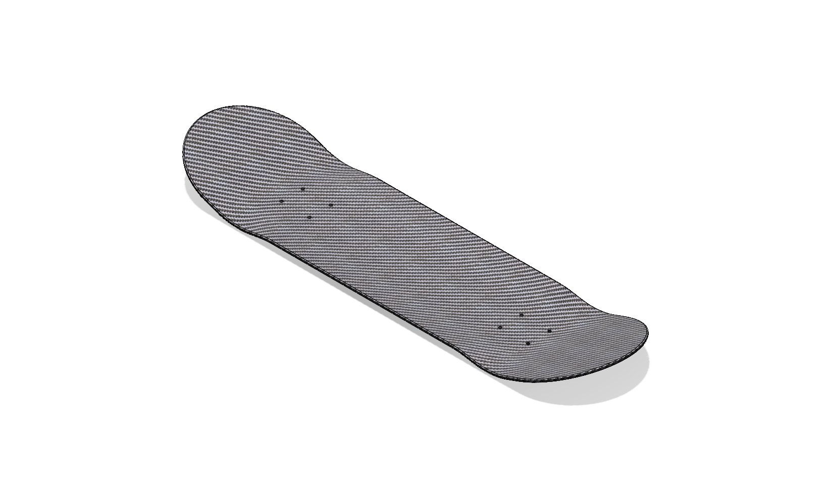
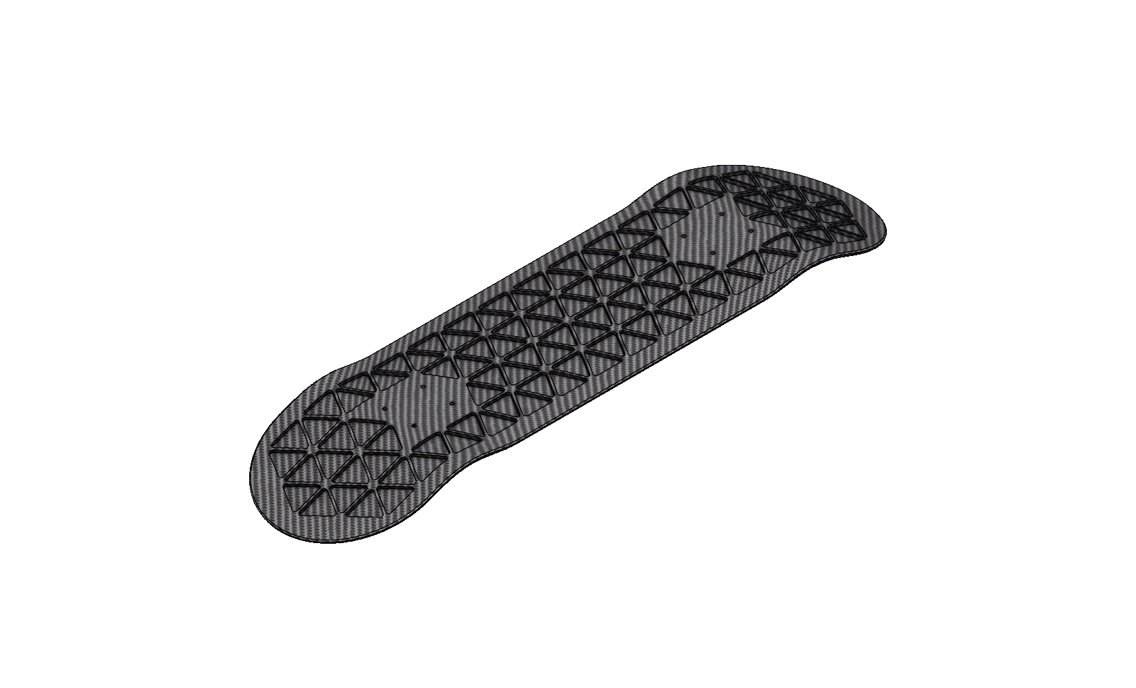
The isogrid carbon fiber skateboard.
Materials Selection Process
The material of the skateboard deck was chosen using the GRANTA Materials Database. The properties of interest in our materials analysis are the Young’s Modulus, or the stiffness of the deck. All initially unsuitable materials, such as ceramics, were filtered out before the materials selection process. A tradeoff-curve was created comparing two performance-indexes: the mass per unit of stiffness vs. the cost per unit of stiffness of the board. For the calculation of the performance indexes in GRANTA, the deck was assumed to act as a beam in bending, where the cross-sectional area of the deck was a “free” variable that could vary with material choices while the length. A penalty function was created to select the best performing materials:
where is the unitless penalty function, and are exchange constants with units and respectively. in and in are the performance indices of the two objectives. The best material will be the one with the lowest value because then and are minimized.
Following we can rearrange to find the equation of a line on the tradeoff-curve:
Where is the slope which can be adjusted to fine-tune the included materials. In my materials selection process, to bias the penalty function in favor of stiffer but more expensive materials.
The plots for both the tradeoff-curve and a second filtering step are shown below:
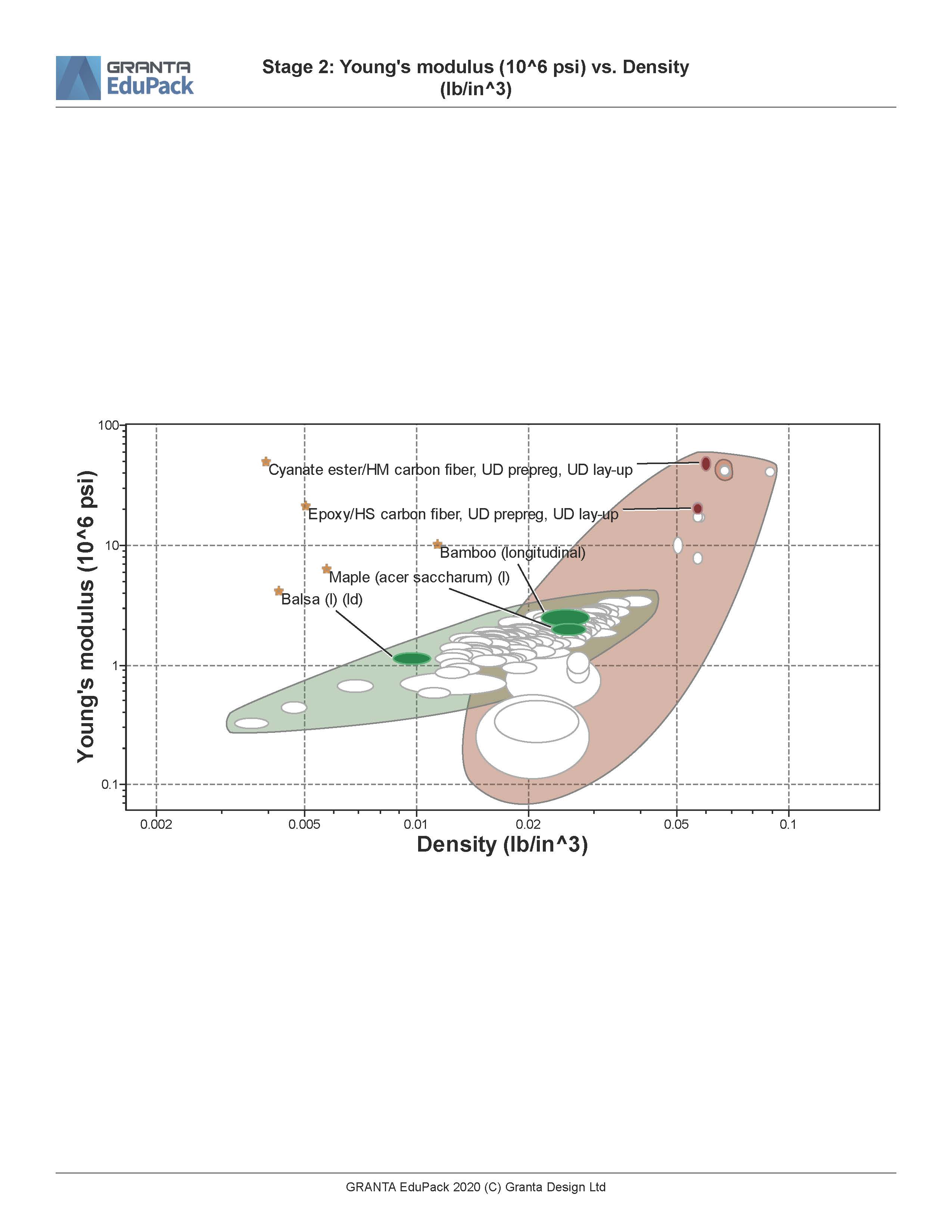
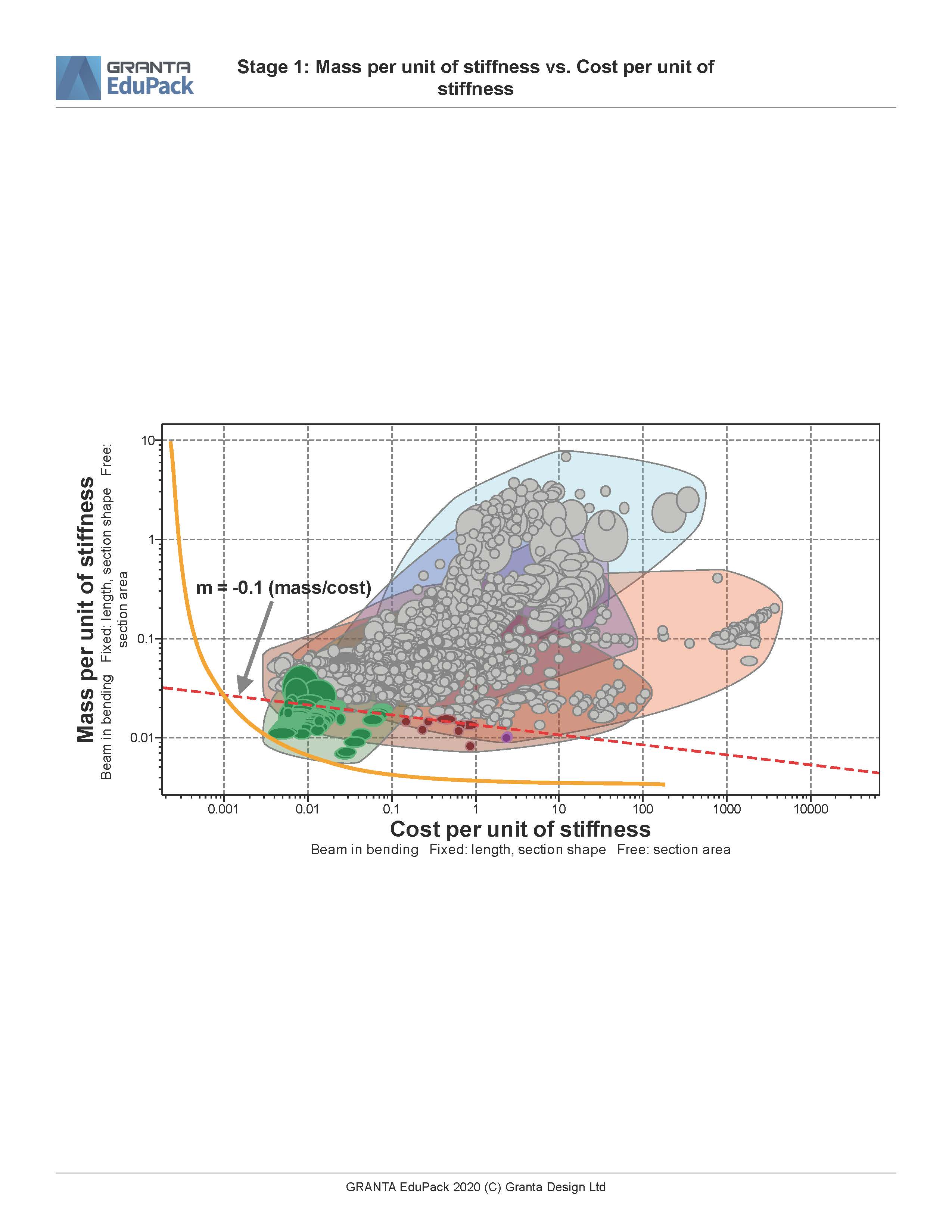
The tradeoff-curve and the materials selection plots.
Bamboo, Balsa wood, and two carbon fiber composites were selected to be part of the design study. The composite nature of these materials allows them to be very strong in tension. The Maple material serves as a reference because pressed Maple plywood layers are commonly used to make skateboard decks.
Analytical Solution
Before using finite element analysis to simulate the skateboard deck deflection in detail, it is helpful to solve for the static simulation analytically. An analytical check of our solution allows us to ensure that the simulation is returning reasonable values for the maximum deflection.
A simply supported beam with a point load applied to its center the maximum deflection is shown below. is the applied force, is the total length of the beam, is the deflection angle and is the beam deflection.

Deflection Diagram for a simply supported beam.
The equation,
where is the Young’s Modulus and is the area moment of inertia can be used to find the maximum deflection. The area moment of inertia of the deck can be calculated using:
where is the width of the deck and is the deck thickness. The cross section of the deck is simplified to be rectangle with a width of and variable thickness. The length of the skateboard is set to be , the distance between the truck axles. The isogrid pattern is ignored when analytically calculating the maximum deflection of the deck. Using the above values and equations and , the maximum deflection for our two materials of interest are calculated below:
| Material | Deck Thickness, | Area Moment of Inertia, | Young’s Modulus, | MAX Deflection, |
|---|---|---|---|---|
| Maple (acer saccharum) (l) | ||||
| Epoxy/HS carbon fiber, UD prepreg, UD lay-up |
We expect the deflection of the deck in the FEA simulation to be smaller than these analytical estimates because the force of the rider is distributed across the area of the rider’s foot.
FEA Simulation
The simulation of the skateboard deck deflection was performed in SolidWorks. A pin and slider joint ere placed in “test” trucks mounted below the board respectively. A downwards force was applied to the center of the board to an area of a size 12 shoe . This force defines the worst-case scenario where the rider is pushing the skateboard and all of their weight is positioned above the center of the board. For the purposes of this simulation, it was assumed that the heaviest rider would have the maximum shoe size of 12. Hinge fixtures were added at the location of each “test” truck. First, a simulation was conducted with the Maple material with the isogrid weight saving pattern removed. The deck thickness parameter was reduced until either the safety factor or the vertical displacement of the board stopped meeting their requirements. The simulation was then performed with the isogrid pattern enabled using the Epoxy/HS carbon fiber, UD prepreg, UD lay-up material. The results are tabulated as follows:
| Material | Deck Thickness | MAX Deflection | MIN Safety Factor | Deck mass |
|---|---|---|---|---|
| Maple (acer saccharum) (l) (no isogrid) | ||||
| Epoxy/HS carbon fiber, UD prepreg, UD lay-up (no isogrid) | ||||
| Epoxy/HS carbon fiber, UD prepreg, UD lay-up (with isogrid) |
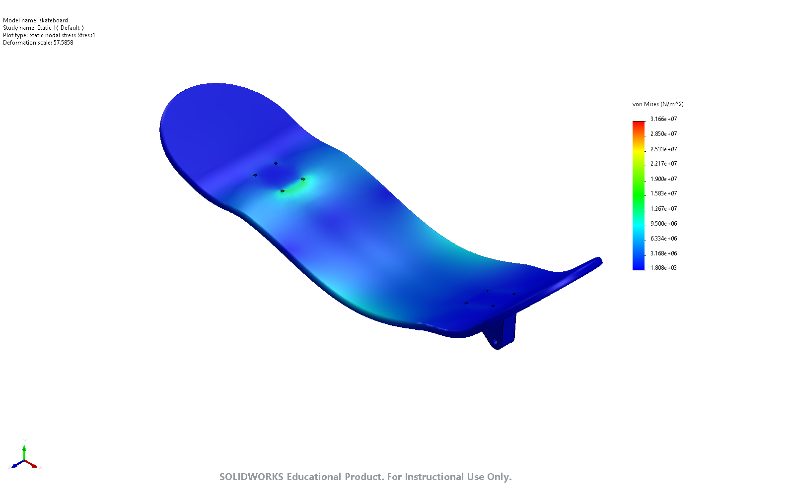
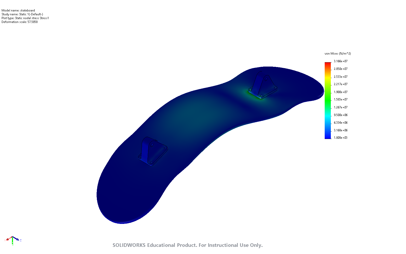
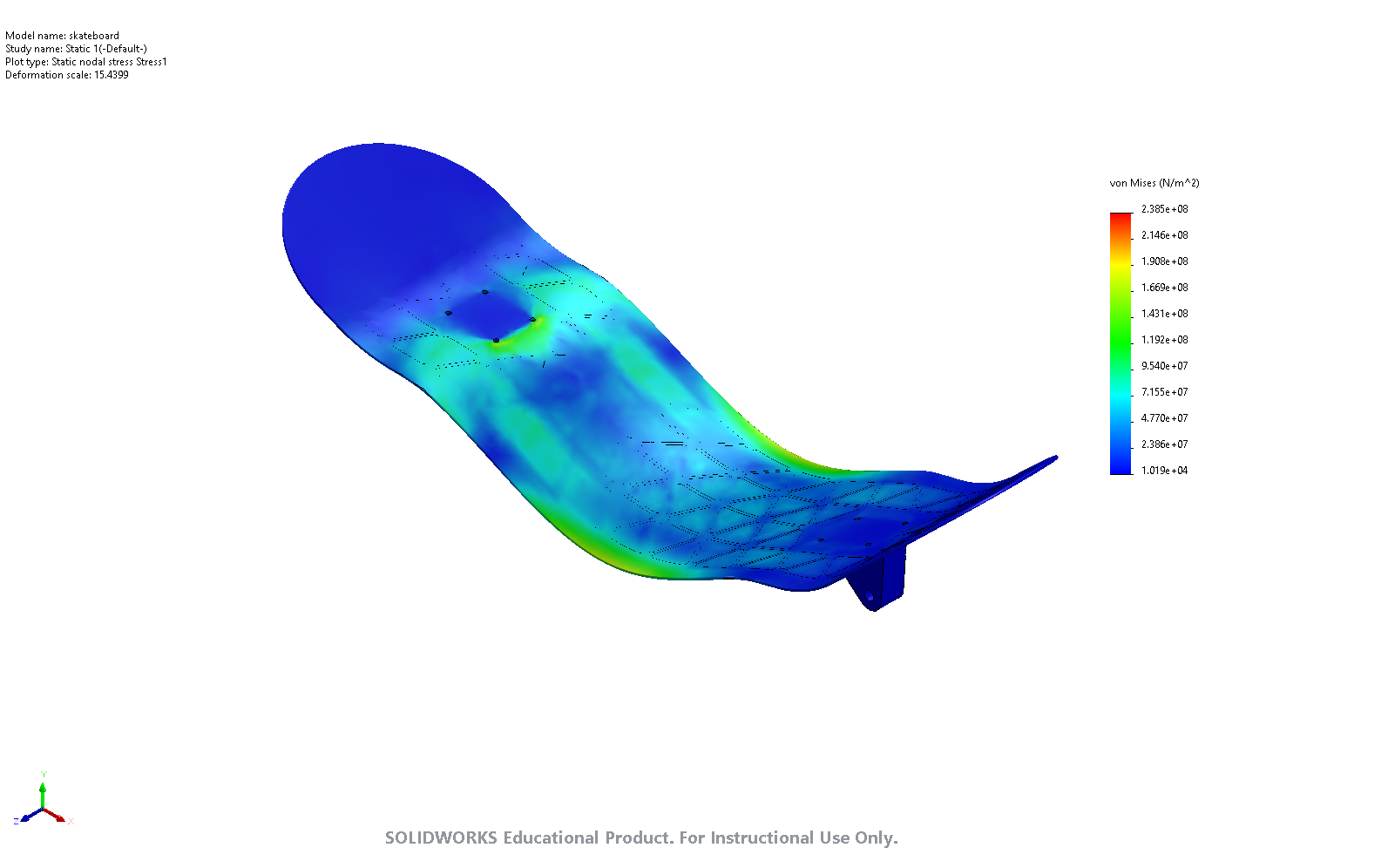
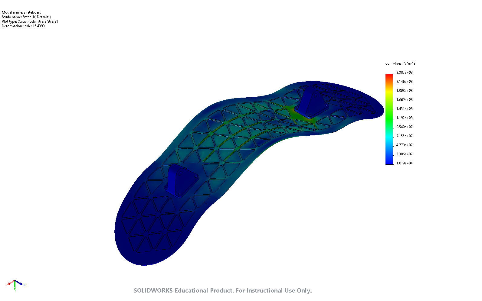
Carbon fiber’s excellent tensile strength allows it to excel as a skateboard deck material. The isogrid pattern debossed on the bottom of the board significantly reduced the deck mass while still meeting the factor of safety and the deflection requirements. As seen in the simulation, the isogrid pattern distributes the internal stresses due to the applied load more evenly throughout the board. Ultimately, the choice of a carbon fiber material, and the use of the isogrid weight reduction pattern allowed the final skateboard deck to be more than 3 times lighter than its wooden counterpart.
It is clear from these results why Maple is overwhelmingly the material of choice in skateboard decks. Thanks to its composite structure, maple offers excellent stiffness at a very low cost. With the use of multiple ply layers pressed and glued together during the maple deck construction process, the maple gains additional strength in tension. Although carbon fiber decks are much stiffer for the same thickness, they are more difficult to manufacture. The benefit of using carbon fiber as a skateboard deck material could be explored in more detail with the design an manufacture of a physical prototype. Other issues like creep and long-term durability, which are difficult to simulate could be tested. Although simulations can be helpful because they eliminate the need to manufacture every prototype iteration, live displacement and stress tests must still be performed before a new skateboard deck design can be deemed safe.