Table of Contents
For our final project in ME360 we were tasked with designing and building a 2.5 axis motion system. Our team of four chose this system to perform the task of plotting a time on a whiteboard and erasing it at one minute intervals. The project is accompanied by the following constraints:
- The work volume is limited to a cube of .
- The system must be small and light enough to be easily carried in a backpack. The device may be totally or partially disassembled for transport as long as it can be assembled by one person in no more than 10 minutes.
Interested in experimenting with unconventional 2 axis motion systems, we decided on utilizing a parallel linear motion system with a linkage design to connect the two axes to plot on the whiteboard. The motion system is pictured below:
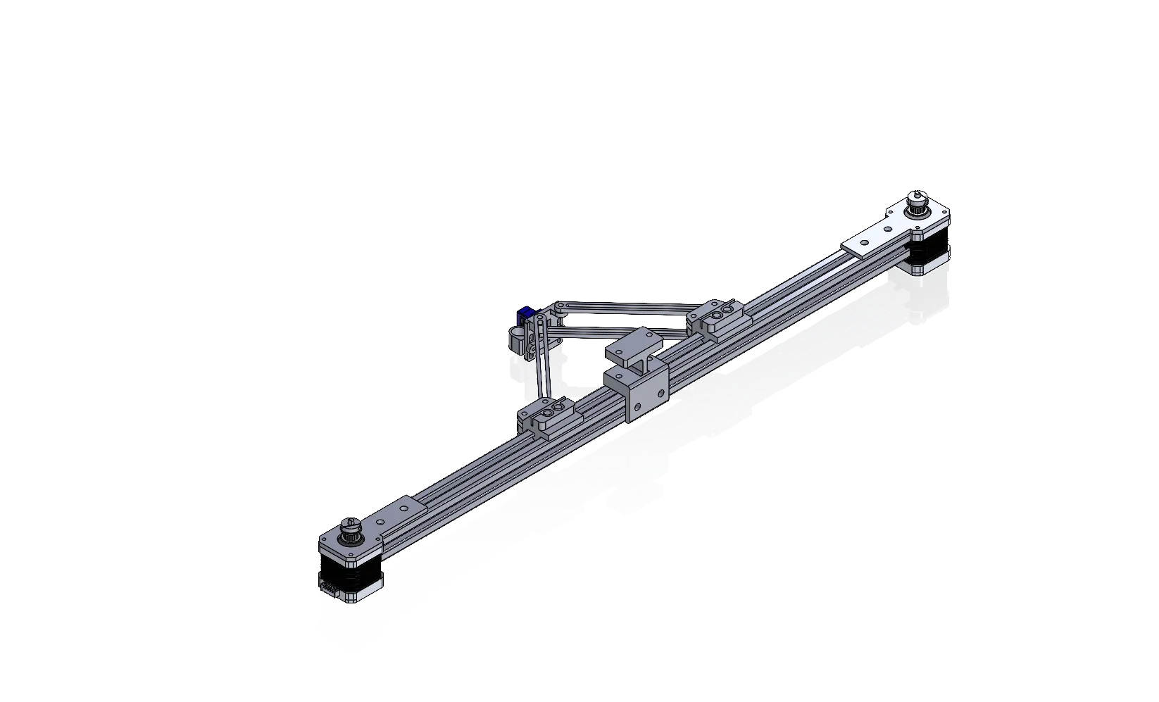
The 2 axis motion system used in the plotter. Each axis consists of an independently-actuated linear rail. The two rails are connected together using linkages.
Each axis can be individually actuated and combinations of actuations of the left and right axis will produce various movements of the pen plotter mounted at the intersection of the left and right linkages. The CAD files for the entire plotter robot including part drawings can be downloaded here.
Mechanical Design
Linear Stages
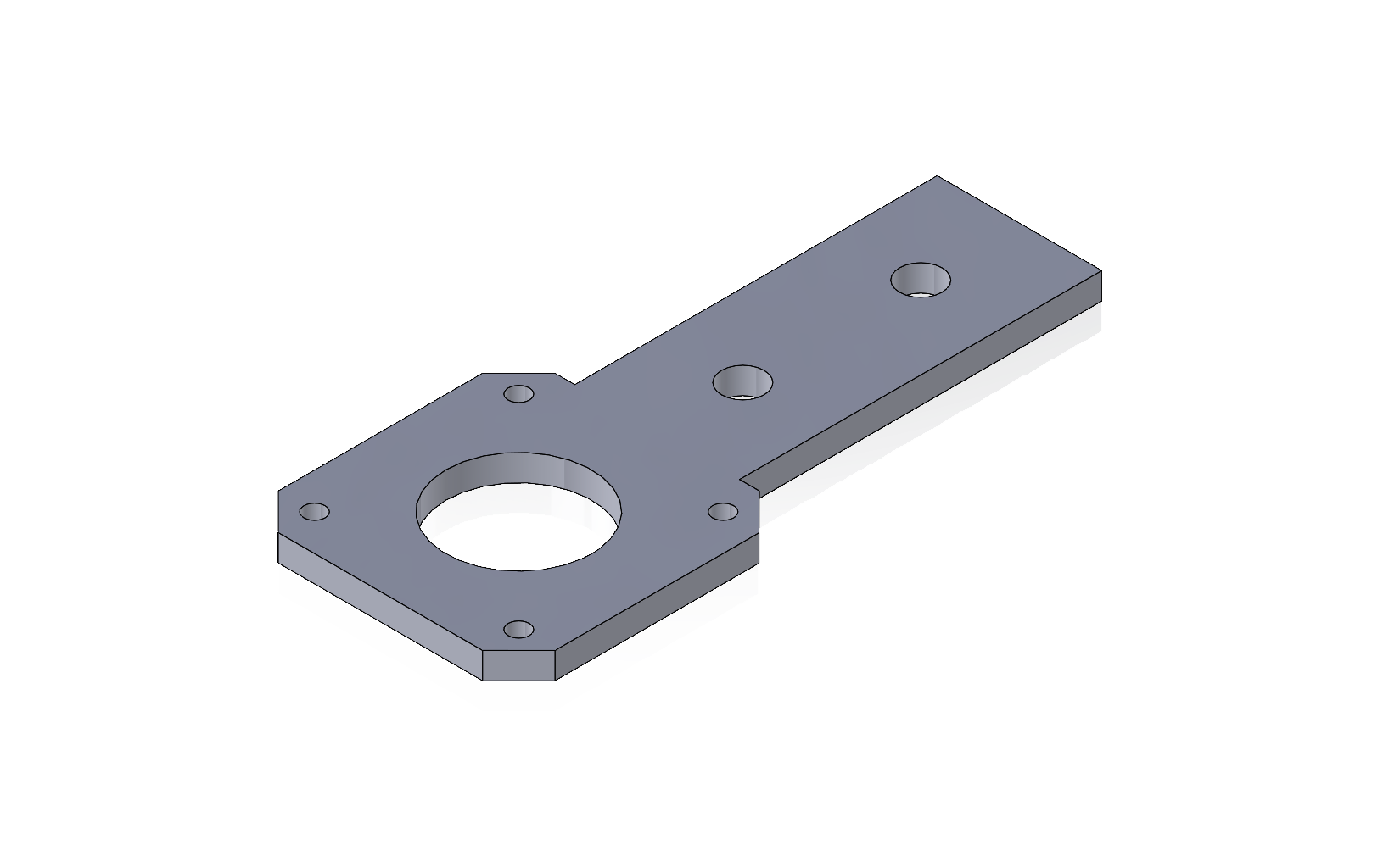
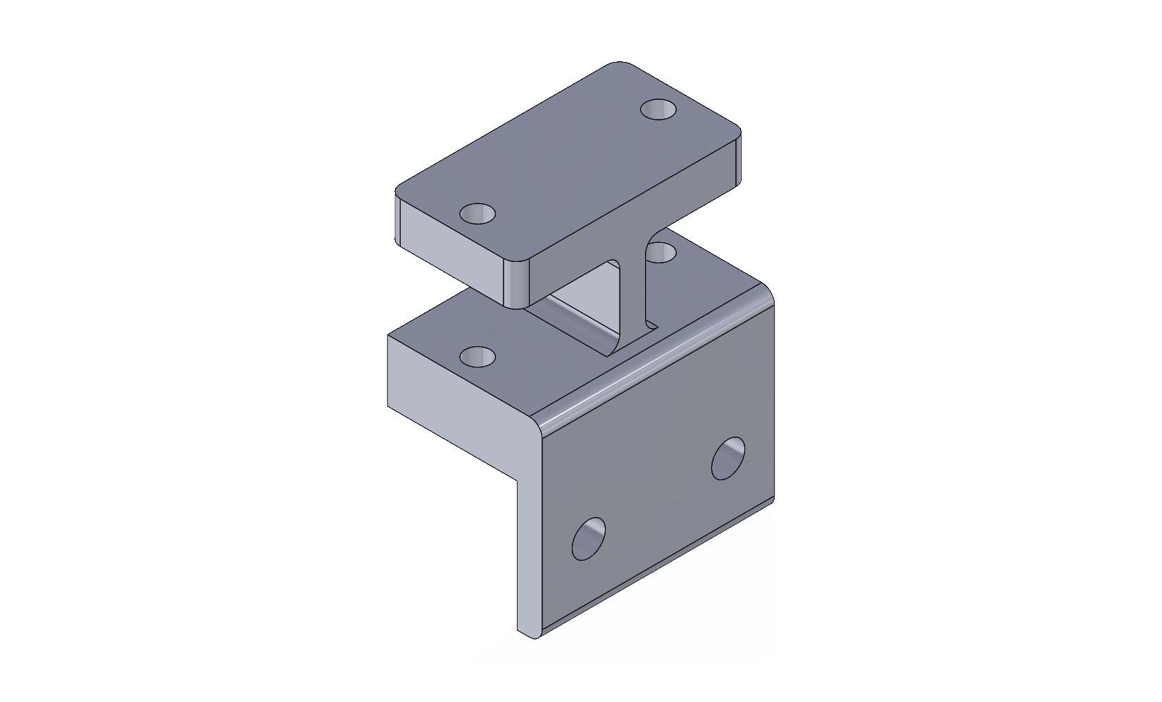
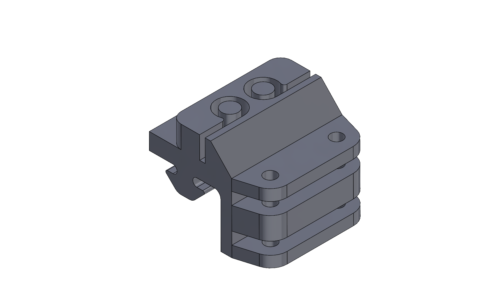
The plotter is comprised of two symmetrical timing belt-driven linear stages mounted to a 80/20 linear rail. NEMA 17 stepper motors are mounted to the linear rail using a 3D printed mounting bracket. The mounting bracket functions as a means of securing the stepper motor to the linear rail and as a means of tensioning the timing belt. Pulling the stepper motor back and tightening the mounting bracket tensions the belt. The two belts are attached to idler pulleys mounted to a center bracket in the middle of the 80/20 rail. Finally, the belt is attached to a carriage with slots designed to hold the timing belt in place at its ends. When the stepper motors rotate, the carriage travels up and down the linear slide due to the motion of the belt. All three components are pictured below:
Selector Mechanism
The selector mechanism enables switching between a drawing and erasing mode using a servo and a linkage with slots at its ends. The servo output is directly attached to a linkage which rotates, moving pen and eraser holders on either end of the linkage up and down along their respective slots. The complete selector mechanism is shown below:
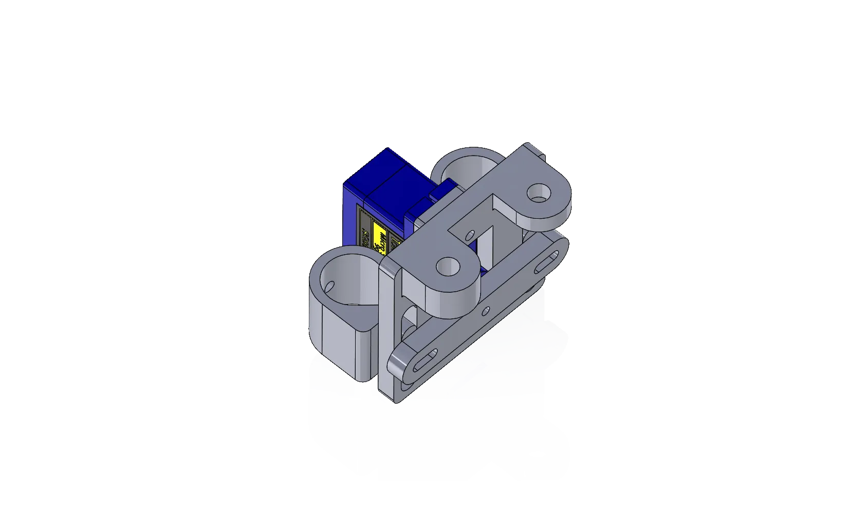
The end effector mechanism is actuated using a servo and a linkage with pin slots on either side for a pen and eraser holder.
In order to minimize the moment of inertia of the end effector, the selector mechanism is designed to be as compact and light as possible. The linkages from the linear rail carriage attach to the selector mechanism at its top. In order to keep the end effector parallel with the linear rail, a parallel four bar linkage is used to attach the selector mechanism to one of the carriages. The other carriage attaches to the selector mechanism using one simple singular link.
Robot Kinematics
Because the kinematics of this parallel linear motion system are not the same as for a pure cartesian system, they must be solved for in terms of the displacement of each axis to find the absolute position of the end effector in terms of the variables and . If we name the displacement of each parallel axis as and respectively, the kinematic equations of the system in terms of the general coordinates and are as follows:
Where is the length of the linkages used.
Solving for and in equations and we find:
We can use these kinematic equations to solve for the positions of each parallel axis for any value of and . A simulation of the plotter movements performed in SolidWorks is shown below:
A simulation of the plotter plotting an arbitrary line segment.
Programming
Using the derived equations of motion and we can write a program that moves the plotter end effector to any cartesian coordinate position. The plotter program is written in C++ using platformIO, an embedded development platform which supports the Atmega 328p and the Arduino framework. The program is described in detail on the project GitHub.
The timebot plotter program enables the plotting and erasing of any numerical character and the : delimiter by emulating an alphanumeric 7 segment display. The time and numbers can be drawn to any location on a whiteboard specified by an and starting origin. Future revisions could include the plotting of other two-dimensional data from SVG files, or adding support for G-CODE commands.
Completed Prototype
A video of the completed robot prototype can be viewed below. To calibrate itself against a known reference position, the robot moves both of its linkages against the idler in the center. Once this homing step is complete, the robot is ready to begin plotting.
The plotter robot demonstrating its ability to plot an arbitrary time. In
this example, the robot plotted 12:34.
Future Work
Although the plotter was able to plot any number on the whiteboard successfully, improvements can be made to the mechanical design of the plotter and the program to enable faster, cleaner, and more advanced plotting. Because the linkages were made of PLA plastic, the plotter end effector was not stiffly attached to the carriage, leading to some artifacts in the plotted numbers. A possible improvement could include adding a caster wheel to the bottom of the end effector to allow its weight to be supported by the whiteboard instead of by the linkages. Switching from PLA plastic to a stiffer material such as aluminum could also improve the stiffness of the entire plotter. Because of the irregular kinematics of this system, standard 3D printer firmware such as Marlin combined with G-CODE commands for positioning could not be used. Future efforts in improving the programming could be dedicated to modifying the Marlin 3D printer firmware to make it compatible with the kinematic parallel two axis linear motion system seen here.