Table of Contents
Cartesian plotting mechanisms are commonly used to illustrate a mechanism capable of motion with two degrees of freedom. The ink in the felt tip pen used for plotting drying up as a result of being left uncapped is a common issue in many pen plotter designs. In this project, I explore a 1 DOF adjustable plotter pen mechanism that is able to accommodate and cap a pen of various sizes. Additionally, by varying the travel of the pen deployment mechanism, the amount of pressure that the pen applies to the pen can be adjusted. Solidworks CAD files for the plotter pen mechanism assembly can be downloaded here.
Mechanism Design
The plotter pen mechanism was designed according to the following constraints:
- The pen will write on a horizontal flat surface that lies 1cm below the mounting surface. No part of the mechanism shall extend below this surface when the pen is in the stored position.
- The pen must be positioned vertically with its tip pointing downwards at each of the two extreme positions.
- The pen will execute its motion in , stop to stop.
- For the purposes of calculating motor torque specifications, the links will be assumed to be made of AISI 1020 steel.
A parallel four bar linkage is used to move the pen from its capped to deployed position. The linkage supports the pen on both sides to increase the stiffness and robustness of the design. Each intermediate linkage has bent mounting points to allow the arms to overlap without interfering with each other during their movement. One of the four linkages attaches to the motor directly by means of a hole profile matching that of the stepper motor. Each linkage is long to allow the pen to move at least vertically. Both linkages are shown below:
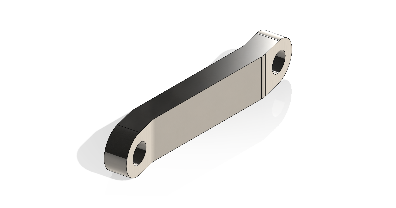
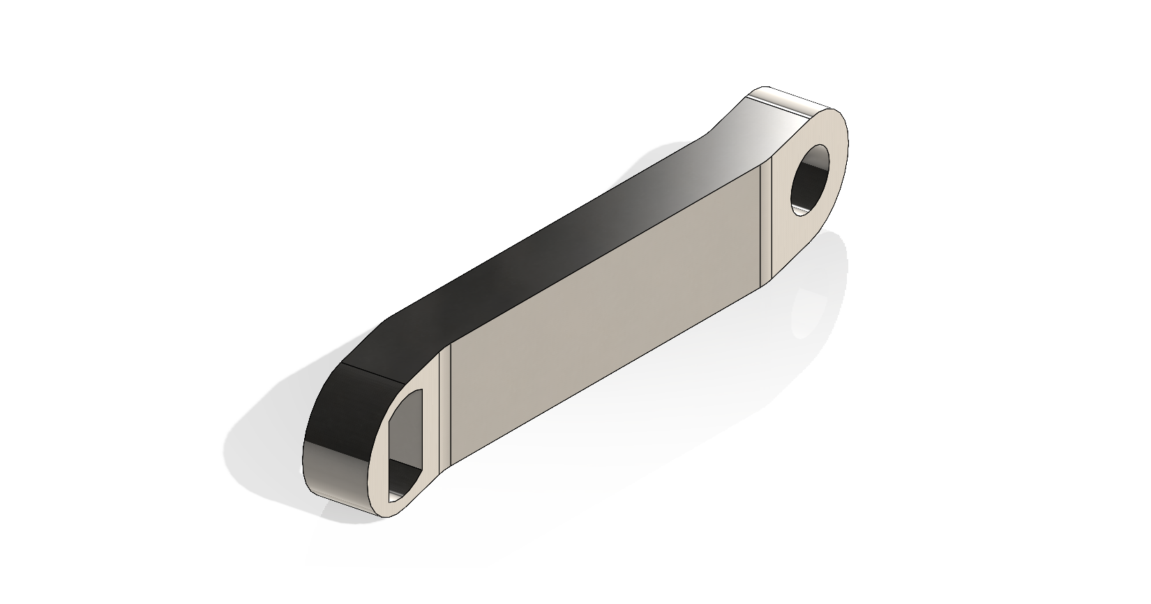
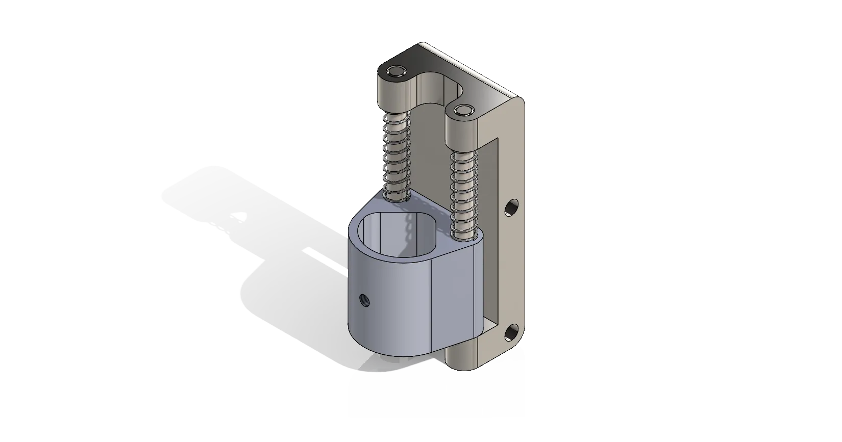
The pen is placed in a mount that, because of its geometry, accepts various pens with a diameter of up to . The pen mount fixes the pen inside a semi-circular cavity hole. A 4-40 hex button head screw pushes the pen against the back of the mount, fixing it in place. In order to enable the application of variable pressure to the plotting surface, the pen mount is constrained to move vertically along a long, diameter linear rail. The pen mount must be manufactured out of nylon for good low-friction performance. long springs are positioned at the top of the linear slide enable the application of up to to the plotting surface. The pen mount and the variable pressure mechanism is shown below:
The linkages attach to the back of the pen mount carriage using a long diameter rotary shaft. A press fit must be used to attach the rotary shaft to the carriage and a free fit should be used to attach the shaft to the linkage arms.
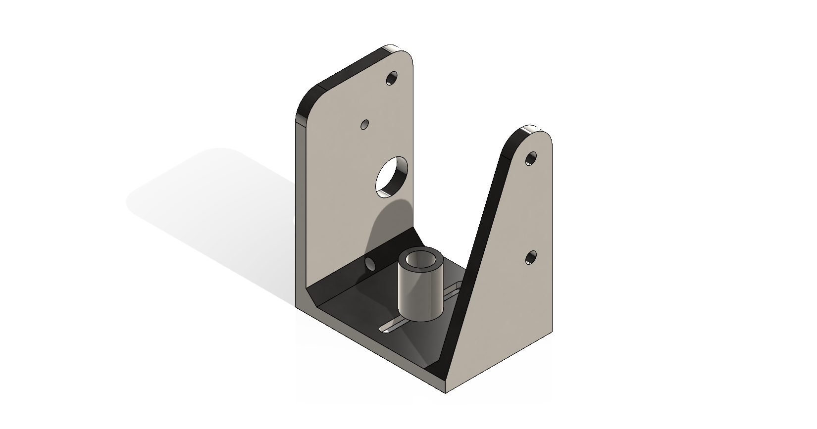
In order for the mechanism to be used with a variety of pens, the pen cap position must also be adjustable depending on the length of the pen and its mounting point in the pen carriage. A custom adjustable pen cap was designed to ensure that the pen always maintains a consistent seal during its motion. The pen cap is mounted along a linear slot and can be adjusted by tightening a 4-40 hex button head screw mounted to the bottom of the cap. The mechanism is shown below:
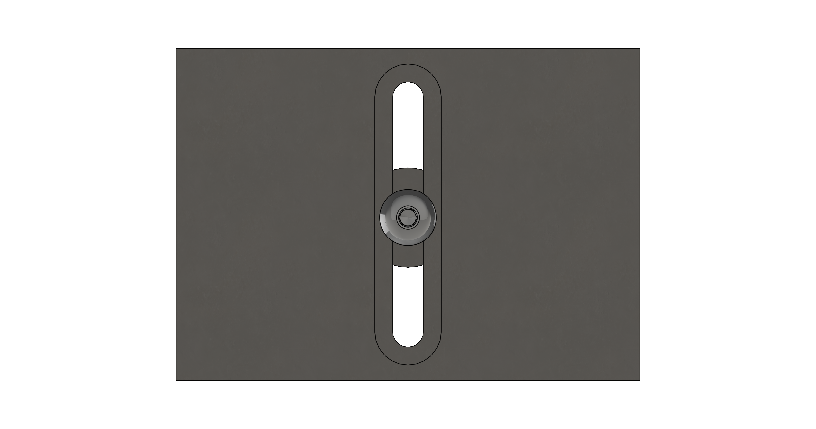
The travel distance of the plotter pen mechanism will vary depending on the pen used and the desired pressure applied to the plotting surface. For a standard Sharpie pen, the motor should move from its initial starting position inside the adjustable cap to achieve the required vertical travel distance of .
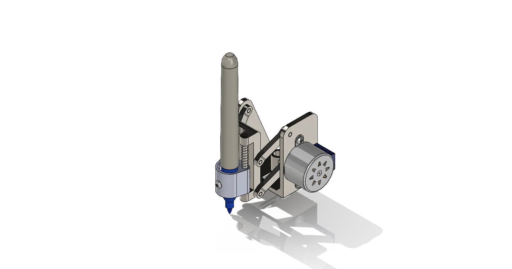
Animations of the pen plotter mechanism deployment movement.
Motor Specifications
By performing a motion analysis study in Solidworks, motor specifications and torque requirements can be determined. In this simulation, it was assumed that all linkage components were manufactured from AISI 1020 steel. Forces due to gravity were included in the motion analysis. The magnitude of the torque required to move the linkage in stop-to-stop is shown below:

As expected, the point of peak torque occurs at the beginning of the linkage motion. This value is simulated to be . The 28BYJ-48 5V stepper motor outputs a maximum torque of . Because this value matches the maximum torque simulated in the motion study, the 28BYJ-48 stepper motor may not be suitable in this design, depending on the mass of the pen being used. In this motion study, the pen was assumed to be made of ABS with a mass of .
The angular velocity of the motor required to move the mechanism is also an important quantity that must be determined. The maximum angular velocity of the motor must be in order to achieve the desired motion in . This value will change depending on the pen size and the desired pressure of the pen against the plotting surface. A plot of the magnitude of the angular velocity of the motor is shown below:

Because the maximum angular velocity of the 28BYJ-48 stepper motor is limited to about , it will not be suitable for use in this mechanism if the desired motion is to be achieved in .